Proven Reliability of Chicago Clamp Systems: Load Capacities & Safety
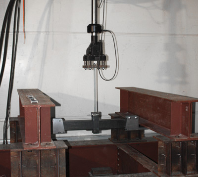
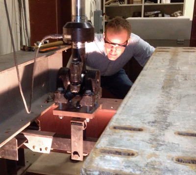
Independent Lab Testing & Load Capacity Tables for Clamp Systems
Each Chicago Clamp System® has been designed, and then rigorously tested by an independent engineering lab, to provide a product on which you can depend. Load tables derived by calculation and testing are conveniently organized in table form.
Suspension Clamp System
Live Load Capacity (pounds) vs. Span of Back-to-Back Angles 1-11
Size of Each of an Angle Pair
Longest angle leg is vertical |
Span (feet) |
| 2 |
3 |
4 |
5 |
6 |
7 |
8 |
9 |
10 |
11 |
12 |
13 |
14 |
15 |
| 2" x 2" x 3/16" |
1,690 |
1,123 |
821 |
635 |
511 |
– |
– |
– |
– |
– |
– |
– |
– |
– |
| 2" x 2" x 1/4" |
2,000 |
1,459 |
1,088 |
856 |
693 |
569 |
– |
– |
– |
– |
– |
– |
– |
– |
| 2 1/2" x 2" x 3/16" |
2,000 |
1,707 |
1,237 |
956 |
769 |
635 |
536 |
– |
– |
– |
– |
– |
– |
– |
| 2 1/2" x 2" x 1/4" |
2,000 |
2,000 |
1,691 |
1,313 |
1,061 |
882 |
748 |
643 |
528 |
– |
– |
– |
– |
– |
| 3" x 2" x 3/16" |
2,000 |
2,000 |
1,645 |
1,270 |
1,020 |
842 |
708 |
604 |
521 |
– |
– |
– |
– |
– |
| 3" x 2" x 1/4" |
2,000 |
2,000 |
2,000 |
1,791 |
1,446 |
1,200 |
1,061 |
873 |
759 |
665 |
587 |
520 |
– |
– |
| 3 1/2" x 2 1/2" x 1/4" |
2,000 |
2,000 |
2,000 |
2,000 |
2,000 |
1,682 |
1,428 |
1,232 |
1,074 |
945 |
837 |
746 |
667 |
599 |
| 4" x 3" x 1/4" |
2,000 |
2,000 |
2,000 |
2,000 |
2,000 |
2,000 |
1,873 |
1,618 |
1,414 |
1,246 |
1,106 |
988 |
886 |
798 |
| 5" x 3" x 1/4" |
2,000 |
2,000 |
2,000 |
2,000 |
2,000 |
2,000 |
2,000 |
2,000 |
1,932 |
1,700 |
1,507 |
1,344 |
1,203 |
1,081 |
Table Notes 1-11
- Two Spanning Angles required per Suspension Clamp System, purchase though your local vendor.
- Angles are back-to-back, but spaced apart by Suspension Clamps.
- Allowable net load, per pair, may be located anywhere along the span. Weight of angles has been accounted for.
- Angle dimensions are listed “Vertical Leg” x “Horizontal Leg” x “Thickness”.
- No values below 500 lbs. are listed. Allowable loads have been limited to 2,000 lbs. maximum.
- Allowable loads are based on 36 ksi minimum yield steel and the AISC specifications.
- A single load equal to the tabulated capacity or multiple loads with a sum equal to the tabulated capacity is allowable.
- Live Load Capacities based on Safety Factor of 2.0.
- Loads in bold (528) are governed by deflection limit of Span/240; (e.g., 0.500″ for 10′ span).
- Tabulated values are based upon the additional bracing provided by Suspension Clamp System.
- Tabulated loads based on vertical loading only.
Joist Grip Framing Clamp System
Allowable Load (pounds) vs. Span a-h
| Tube Size (inches) |
Load Type |
Span (feet) |
| 3 |
4 |
5 |
6 |
7 |
8 |
9 |
10 |
| HSS 4" x 2" x 1/8" |
concentrated |
2,000 |
2,000 |
2,000 |
2,000 |
1,801 |
1,572 |
1,318 |
1,067 |
| uniform |
2,000 |
2,000 |
2,000 |
2,000 |
2,000 |
2,000 |
2,000 |
1,708 |
| HSS 4" x 2" x 3/16" |
concentrated |
2,000 |
2,000 |
2,000 |
2,000 |
2,000 |
2,000 |
1,820 |
1,474 |
| uniform |
2,000 |
2,000 |
2,000 |
2,000 |
2,000 |
2,000 |
2,000 |
2,000 |
Table Notes a-h
- Allowable concentrated load at middle of span. Allowable loads are net (weight of tube has been accounted for).
- Multiple loads, that are symmetrically placed and whose
total equals the tabulated value, may be used.
- The reaction to each clamp bracket must be limited to a net
value of the clamp’s charted capacity.
- Allowable loads have been limited to 2,000 lbs maximum.
- Allowable loads are based on 46 ksi minimum yield steel
(A500, Gr. B), the AISC specification and a safety factor of 2.0.
- Loads in bold (1,067) are governed by applied-load deflection
limit of Span / 240; (e.g., 0.50" for 10′ span).
- Tube’s 4" dimension is vertical. Span is horizontal.
- Tube weights: 4.75 lbs/ft for 1/8" wall, and 6.87 lbs/ft for 3/16" wall. Weights and thicknesses are nominal.
Tube Framing Clamp System
Live Load Capacity (pounds)
| Component Capacities |
Download Positive |
Uplift Negative |
| Allowable Load (pounds) |
| Joist Grip End Clamp |
1,000 |
1,000 |
| T-Bracket |
1,000 |
1,000 |
| InLine End Clamp |
1,000 |
1,000 |
| Girder Clamp |
1,000 |
– |
| Cross Support Bracket |
1,000 |
– |
Edge Tubes
Allowable Span vs. Load & Load-Type a-g
| Size of Rectangular Tube (inches); minor axis bending (a-g) |
Max Load = 500 lbs. |
Max Load = 1,000 lbs. |
| Concentrated |
Uniform |
Concentrated |
Uniform |
| (in.) |
(ft. & in.) |
(in.) |
(ft. & in.) |
(in.) |
(ft. & in.) |
(in.) |
(ft. & in.) |
| HSS 3" x 1.5" x 1/8" |
64 |
5′ – 4" |
81 |
6′ – 9" |
45 |
3′ – 9" |
57 |
4′ – 9" |
| HSS 3" x 1.5" x 3/16" |
73 |
6′ – 1" |
93 |
7′ – 9" |
52 |
4′ – 4" |
65 |
5′ – 5" |
| HSS 3" x 1.5" x 1/4" |
79 |
6′ – 7" |
100 |
8′ – 4" |
56 |
4′ – 8" |
70 |
5′ – 10" |
Table Notes a-g
- Short dimension of tube cross-section is vertical, parallel to load (minor axis bending).
- Allowable, net concentrated load, per tube, may be located anywhere in the span. Weight of tube has been accounted for.
- Allowable uniform load is the net loading on the tube. Weight of tube has been accounted for.
- allowable loads are based on 46 ksi minimum yield steel (ASTM A 500, Gr. B) and the AISC specification.
- All net (applied) loads are governed by deflection limit of Span / 240; (e.g., 0.250" for 5′ span)
- Tube-wall thicknesses are nominal. Minimum is 0.93 times nominal, per 2005 AISC specification.
- Allowable loads ("max" loads) arebased on a safety factor of 2.0.
3 4 suspension clamp, proven reliability, horizontal clamp system, chicago load, vertical clamp system, 7 times tables up to 1000, what is a test tube clamp used for, positive and negative thrust angle, drill press what is it used for, load testing companies in chicago, chicago clamp, chicago clamp company, chicago clamps, clamp proven reliability, industrial clamp durability, reliable clamp systems, trusted clamp manufacturer, clamp performance standards, industrial reliability clamps, long lasting clamp systems, high quality clamp solutions, dependable clamp engineering, proven clamp solutions, clamping test, reliable industrial clamp systems, proven pipe support solutions, heavy duty clamp durability, trusted industrial clamp manufacturer, engineered support system reliability, structural clamp performance standards, Midwest industrial clamp experts, dependable pipe support clamps, Chicago clamp reliability, steel girder clamps, Chicago clamp reliability solutions, clamp load vs proof load